What is an op-amp? Symbol and pins
14 minutes · Intermediate
Simulations and quizzes aren't read aloud; pause when you reach them and try them out.
The operational amplifier (op-amp for short) is the most widely used IC in analog electronics. You'll find it in audio amplifiers, sensor circuits, filters, the feedback circuits of power supplies and measuring instruments. It takes its name from where it was first used: in the 1940s it performed mathematical operations such as addition, subtraction and integration in analog computers.
Symbol and pins
An op-amp is drawn as a triangle. It has at least five connections:
- The non-inverting input (+) and the inverting input (−). These signs aren't supply polarity; they describe what the inputs do.
- The output: the pointed tip of the triangle.
- The supply (+V and −V): not drawn on most schematics, but every op-amp needs to be powered.
What does an op-amp do?
An op-amp amplifies the difference between its two inputs with a very large gain:
Vout = A × (V+ − V−)
The gain is so large that even a difference of just 0.1 mV between the inputs makes the output want to be 10 V. But the output can't go beyond the supply voltage. That's why the output of an op-amp used without feedback is almost always stuck at +V or −V. This behavior is called saturation.
Try it yourself: a simple comparator
The op-amp in the circuit below has no feedback at all. While the sine input is above the reference line the output sticks high, and while it's below the output sticks low. Slide the reference up and down and watch how the width of the square wave at the output changes.
Comparator
If the input (V+) > the reference (V−) the output is high, otherwise low
Input signal
Components
No feedback: the op-amp runs open loop.
Supply and op-amp
Packages and pinouts
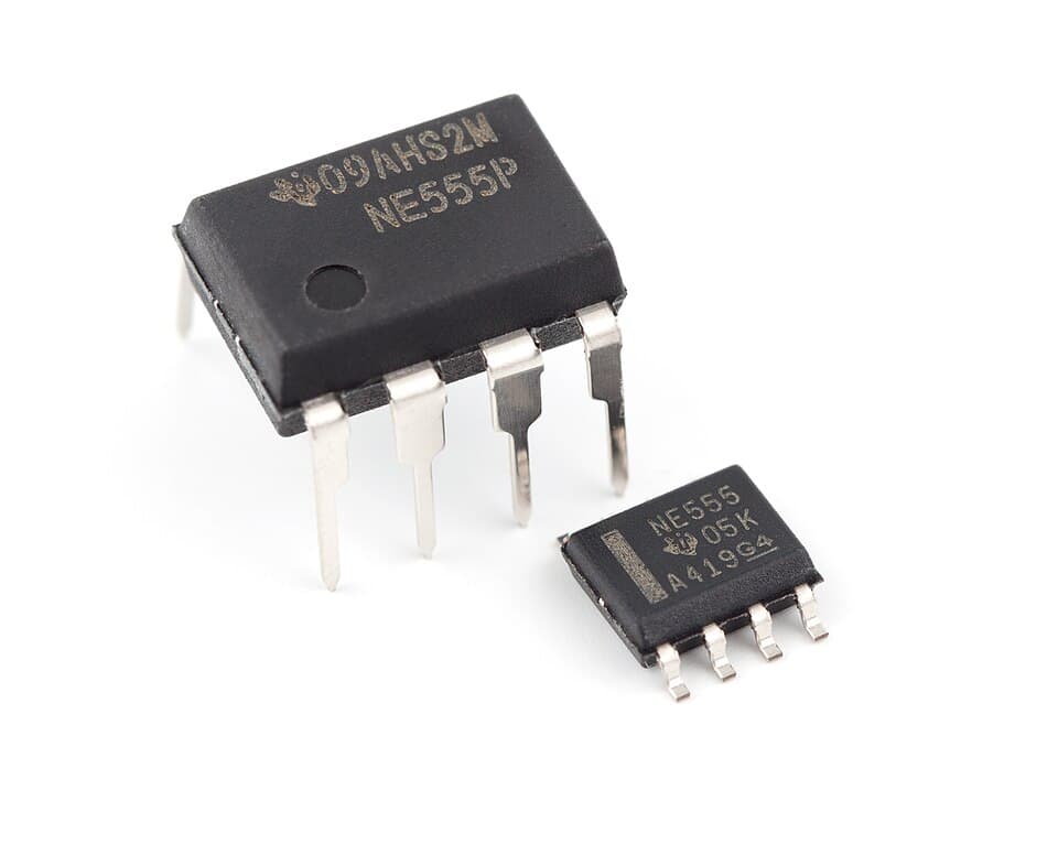
The most common op-amps come in 8-pin DIP or SOIC packages. The pinout of dual models with two op-amps inside is almost standard: the LM358, TL072, NE5532 and MCP6002 are all connected the same way.
1 · Output A ─
2 · Input − A ─
3 · Input + A ─
4 · GND / −V ─
─ 8 · +V
─ 7 · Output B
─ 6 · Input − B
─ 5 · Input + B
📷 LM358 on a real board: which pin is which?
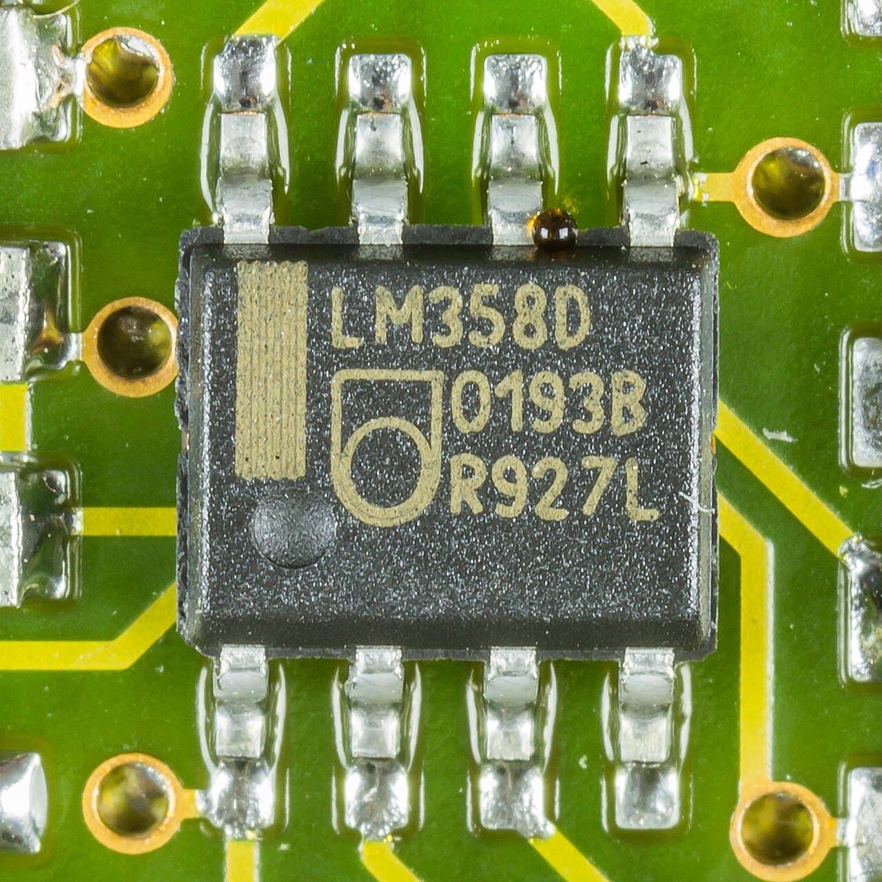 12345678●
- 11 · Output A
- 22 · Inverting input A (−)
- 33 · Non-inverting input A (+)
- 44 · GND / −V
- 55 · Non-inverting input B (+)
- 66 · Inverting input B (−)
- 77 · Output B
- 88 · +V (supply)
- ●Pin 1 mark (round dimple)
Single op-amps are different
On the old but well-known 741 and similar single op-amps the pinout is different: 2 inverting input, 3 non-inverting input, 4 −V, 6 output, 7 +V; 1 and 5 are for offset adjustment. Quad op-amps (LM324, TL074) have 14 pins, with the supply on pins 4 (+V) and 11 (−V). Always check the datasheet before fitting an op-amp.Why are op-amps so common?
Although the gain looks huge and uncontrolled, when we connect the output back to the input through resistors (feedback), those resistors completely determine how the circuit behaves. So we can build whatever gain, filter or mathematical operation we want with a few resistors. In the rest of this course you'll get to know the op-amp as a part, and in the advanced "Op-Amp Circuits" course we'll build each circuit one by one.
Test yourself
1. What does an op-amp amplify?
2. Without feedback, V+ = 2.001 V and V− = 2.000 V. Roughly what is the output? (±12 V supply)
3. Which are the supply pins on an LM358?
4. What do the + and − signs in the op-amp symbol indicate?
This was the free first lesson of the course
The remaining 7 lessons of Meet the Op-Amp, with their simulations and quizzes, unlock when you buy the course.
See the full course →