Inside a microcontroller: CPU, memory, peripherals
16 minutes · Advanced
Simulations and quizzes aren't read aloud; pause when you reach them and try them out.
What actually happens when you write digitalWrite(13, HIGH) on an Arduino? In this course we'll go below the Arduino libraries and program the microcontroller directly, through its registers. First, let's look at what's inside the chip. We'll use the Arduino Uno's ATmega328P as the example.
📷 Real-world view
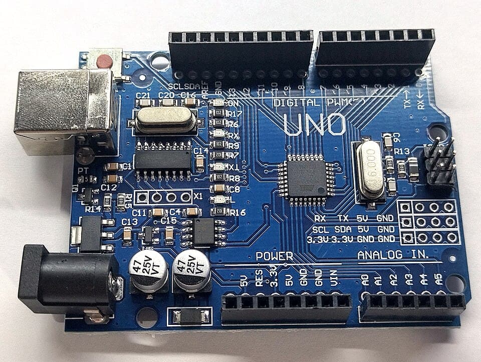
A whole computer inside one chip
CPU core
An 8-bit AVR core at 16 MHz. It executes most instructions in a single clock cycle.
Flash memory (32 KB)
Where the program lives. It isn't erased when the power goes off.
SRAM (2 KB)
The working memory where variables and the stack live.
EEPROM (1 KB)
Small permanent data: settings, the high score.
GPIO ports
Ports B, C and D; each pin can be an input or an output.
Timers
Timer0, Timer1 (16-bit), Timer2: measuring time, PWM, interrupts.
ADC
A 10-bit analog-to-digital converter, 6 channels (A0–A5).
Communication units
USART (serial), SPI and TWI (I2C) hardware.
What is a register?
The peripherals (GPIO, timers, ADC…) are controlled through small 8-bit cells at specific addresses in memory. These are called registers. Each bit of a register is like a switch: setting a bit to 1 makes a pin an output, starts a timer or enables an interrupt.
For example, pin D13 is bit 5 of port B (PB5). A call to digitalWrite(13, HIGH) sets bit 5 of the PORTB register to 1 behind the scenes. Open the register panel in the simulator below and watch bit 5 of PORTB change as the LED blinks.
ARDUINO UNO
virtual board
Registers (bit 7 on the left)
| – | – | D13 | D12 | D11 | D10 | D9 | D8 | ||
| DDRB | 0 | 0 | 0 | 0 | 0 | 0 | 0 | 0 | 0x00 |
| PORTB | 0 | 0 | 0 | 0 | 0 | 0 | 0 | 0 | 0x00 |
| PINB | 0 | 0 | 0 | 0 | 0 | 0 | 0 | 0 | 0x00 |
| D7 | D6 | D5 | D4 | D3 | D2 | D1 | D0 | ||
| DDRD | 0 | 0 | 0 | 0 | 0 | 0 | 0 | 0 | 0x00 |
| PORTD | 0 | 0 | 0 | 0 | 0 | 0 | 0 | 0 | 0x00 |
| PIND | 0 | 0 | 0 | 0 | 0 | 0 | 0 | 0 | 0x00 |
Serial monitor (9600 baud)
🔌 Wiring diagram: which part goes to which pin?
To build this circuit on a real Arduino Uno, wire it as drawn. The red line is 5V, the grey line is GND. While the code runs, the LEDs, servo and buzzer react here too; you can press the drawn button as well.
Why go down to register level?
- Speed:
digitalWritetakes a few microseconds; writing a register directly is a single instruction (62.5 ns). - Capability: the settings for timer interrupts, sleep modes and hardware PWM aren't in the Arduino library.
- Portability: the ESP32, STM32 and every other microcontroller work on the same idea; anyone who understands registers can learn a new chip from its datasheet.
Test yourself
1. Where does the program live on the ATmega328P?
2. Which port and bit does pin D13 correspond to?
3. Where are variables kept while running?
4. How long is one clock cycle at 16 MHz?
This was the free first lesson of the course
The remaining 7 lessons of Microcontrollers: Register-Level Programming, with their simulations and quizzes, unlock when you buy the course.
See the full course →