Power semiconductors: MOSFET, IGBT, thyristor, triac
18 minutes · Advanced
Simulations and quizzes aren't read aloud; pause when you reach them and try them out.
Power electronics is the science of controlling large amounts of energy efficiently: motor speed, lamp brightness, charging current, an inverter's output. The basic idea is to use semiconductors not as resistors but as switches. A switch that's fully on or fully off wastes very little power; the moment of transition in between is where the losses are.
📷 Real-world view
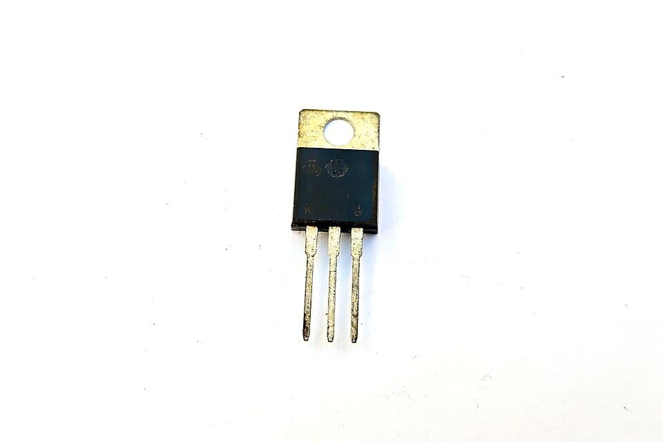
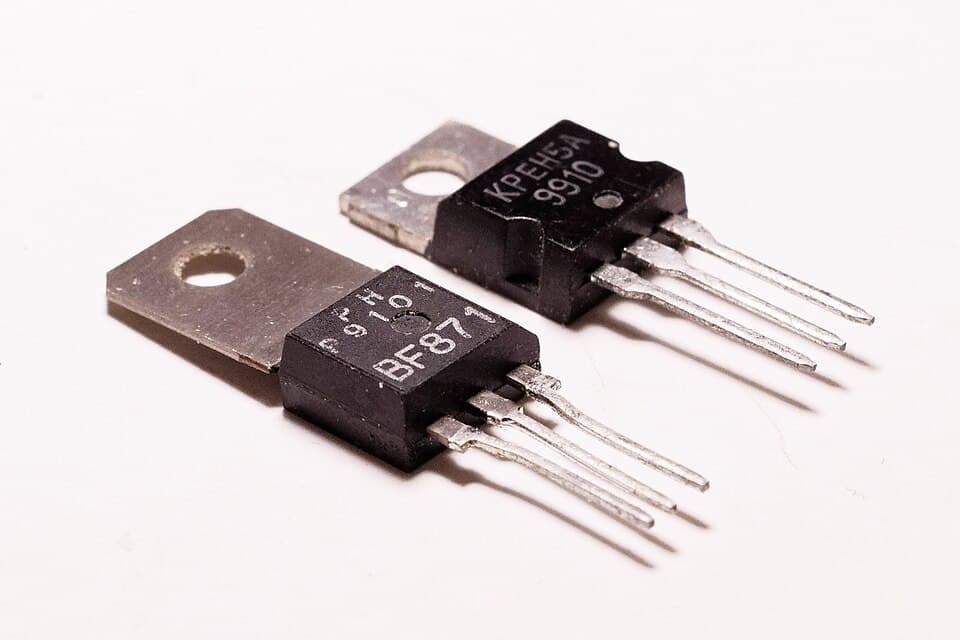
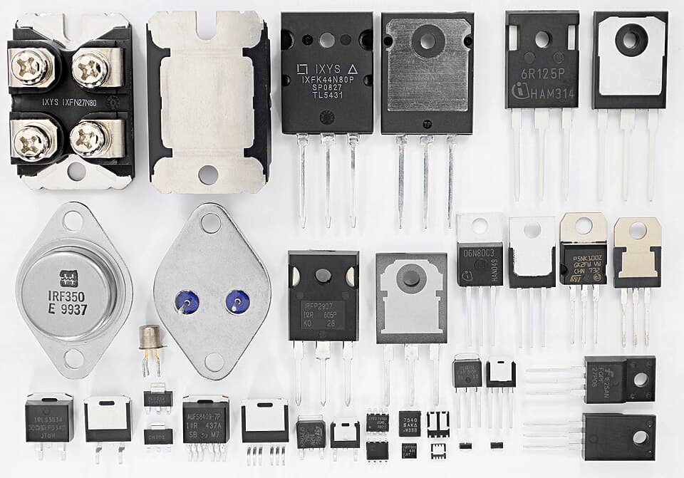
Power switches
| Device | Control | Typical switching | Where? |
|---|---|---|---|
| MOSFET | Voltage (gate) | ~20–200 kHz and above | Low and medium voltage (< 200 V) at high current: motor drivers, DC-DC, inverters |
| IGBT | Voltage (gate) | ~5–30 kHz | High voltage and power (600–1700 V): induction cookers, frequency converters, welders |
| Thyristor (SCR) | Current pulse (gate) | Mains frequency | One-way AC control, soft starters, battery charging |
| Triac | Current pulse (gate) | Mains frequency | Switching and dimming AC loads: lamps, fans, drills |
| SiC / GaN MOSFET | Voltage (gate) | 100 kHz – a few MHz | New generation: fast-charge adapters, electric vehicles, solar inverters |
MOSFET or IGBT?
A MOSFET that's on behaves like a resistor: its loss is I² × Rds(on). An IGBT that's on behaves like a diode: an approximately constant 1.5–2 V drops across it, and its loss is I × Vce(sat). At low voltage Rds(on) can be very small, so the MOSFET wins. At 600 V and above, a MOSFET becomes very large to achieve the same Rds(on); here the IGBT is more economical. The IGBT's disadvantage is that it turns off slowly (the "tail current"); that's why its frequency is limited.
Thyristors and triacs
A thyristor (SCR) turns on when a short current pulse is applied to its gate, and stays on by itself until the current through it falls to zero. The gate has no effect on turning it off. On AC mains the current passes through zero every half cycle, so the thyristor turns off by itself. A triac is a thyristor that can conduct in both directions; it's used for AC loads.
Why switching rather than linear?
If we drive a motor needing 6 V and drawing 10 A from 12 V with a linear transistor, the transistor dissipates (12 − 6) × 10 = 60 W of heat. If we drive the same motor with 50% duty PWM, the transistor is either fully on (e.g. 10 A × 0.01 Ω = 1 W) or fully off (0 W). The efficiency rises from 50% to over 95%.Key values (datasheet)
- Vds / Vce (maximum voltage): choose at least 1.5 times the highest voltage in the circuit; there are sudden voltage spikes during switching.
- Id / Ic (current): the value on the front page of the datasheet is usually measured at a 25 °C case temperature with ideal cooling. In practice, count on half of it.
- Rds(on) / Vce(sat): sets the conduction loss. Rds(on) rises with temperature (~1.5 times at 100 °C).
- Qg (gate charge): sets the drive power and switching speed; next lesson.
Test yourself
1. What is the typical choice for a 600 V, 50 A motor driver?
2. How does a thyristor turn off?
3. What does the loss of a MOSFET that's on depend on?
4. Which device is used in an AC lamp dimmer?
This was the free first lesson of the course
The remaining 7 lessons of Power Electronics, with their simulations and quizzes, unlock when you buy the course.
See the full course →