Inside the breadboard
12 minutes · Intermediate
Simulations and quizzes aren't read aloud; pause when you reach them and try them out.
A breadboard is a plastic board full of holes that lets you build circuits without soldering. You plug parts into the holes, try the circuit, and if you don't like it you pull it apart and build it again. Almost every electronics enthusiast builds their first circuit on a breadboard. But if you use it without knowing how it's wired inside, even the simplest circuit won't work.
📷 Real-world view
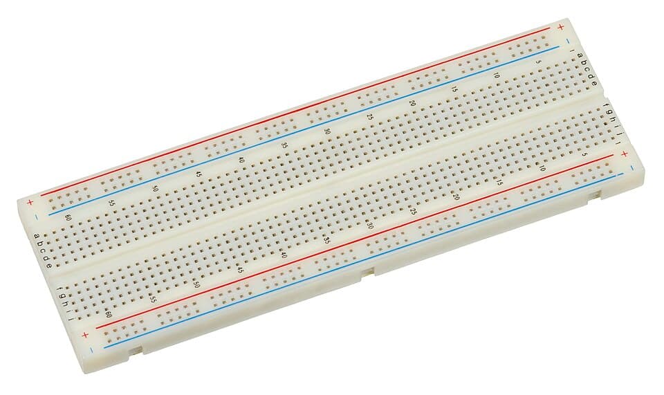
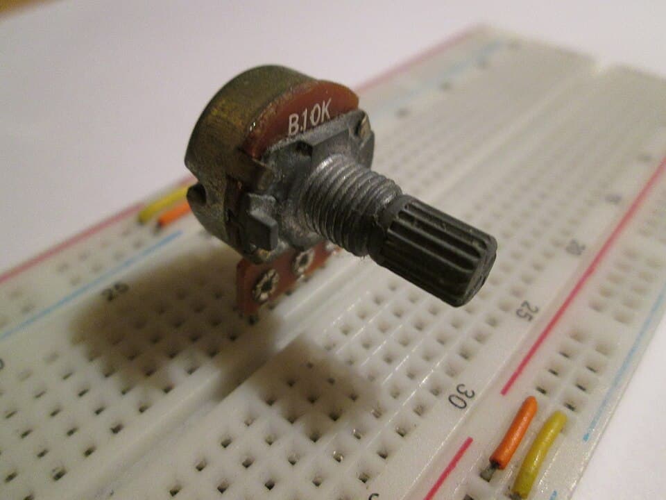
What's inside?
Under the plastic, lined up with the holes, are springy metal strips. A leg pushed into a hole is gripped by the strip. All the holes on the same strip are connected to each other, as if there were a wire between them. The whole secret of using a breadboard is knowing which holes share a strip.
Three areas
Main area: vertical groups of 5
The a-b-c-d-e holes in each column are connected. So are f-g-h-i-j. Neighboring columns are not connected to each other.
The center gap (trench)
It separates the top and bottom blocks. Column 12 on top and column 12 below are not connected. ICs sit across this gap so that each pin ends up in its own column.
Power rails
The long rows along the edges are connected horizontally from end to end. The rail with the red line is used for positive (+), the one with the blue line for negative (−, ground).
Try it yourself
Hover over or tap the holes. The holes that light up green are connected inside to the one you chose. Then, on the "Correct build" tab, trace the path of the current by touching the holes.
Click a hole or hover over it: every hole it's connected to inside lights up green.
Tip: hover over the holes to see which ones the wires and legs are in.
Sizes and limits
- There are full-size (830 holes), half-size (400 holes) and mini (170 holes, no power rails) versions. A half-size board is enough to start with.
- Breadboards aren't suitable for more than about 1 A. The thin metal strips heat up. Don't power high-current loads such as motors straight through a breadboard.
- A small capacitance forms between neighboring strips. With very fast signals, such as radio frequencies, the circuit can become unstable. It's not a problem for beginner circuits.
- Mains voltage is never connected to a breadboard.
Jumper wires
Jumper wires are used to connect holes that are far apart. Flexible wires with ready-made tips are quick but make the circuit a tangle. Solid-core wires cut to length and lying flat on the board keep the circuit tidy. 0.5–0.6 mm solid bell wire is ideal for this.
A new breadboard is tight
Pushing legs into a new board can be hard. Push the leg straight down into the very center of the hole. Straighten thin, bent legs with pliers. If you force parts with thick legs (big diodes, power connectors), the metal strip widens and that hole never grips well again.Common mistakes
- Plugging both legs of a part into the same column. The two legs are connected inside and the part is shorted.
- Thinking the same-numbered columns of the top and bottom blocks are connected.
- Assuming the power rails run unbroken from end to end. On some boards they're split in the middle.
Test yourself
1. In the main area, which holes are connected to each other?
2. Are hole c7 and hole h7 connected?
3. How are the holes on the power rails connected?
4. Why are ICs plugged in across the center gap?
This was the free first lesson of the course
The remaining 8 lessons of Breadboarding and Soldering, with their simulations and quizzes, unlock when you buy the course.
See the full course →